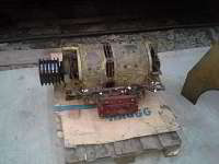
"As you surely know, the Westinghouse YG40C is a combination of the auxiliary generator and the exciter.
The first has 4 brushes and has been already cleaned and repaired it in April, as already reported (see below).
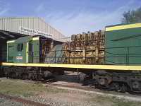
Now in this month of November and after having spent a lot on time on our GE #4036 locomotive, I had time to care for the exciter. This one is also only to be serviced when the complete YG40C is disassembled from the loco.
In fact, the exciter has more brushes than the auxiliary generator and its function principle is totally different as it is primarly meant to excite the main 480 Generator.
The exciter itself has 6 poles windings for its own electrical excitation.
4 of them have a unique winding per pole.
The windings of each of these 4 poles are connected in series and are fed by an external circuit (Positive). As 4 poles are involved in this circuit, current level here does not need to be high (approx. max 7A) and consequently it is possible to fine tune the output of the exciter anchor very precisely which mainly controls the output of the main generator. This circuit is fed by the auxiliary generator and involves for example the carbonstat, a system which is able to limit the current in the case the prime mover should be overloaded.
The next 2 poles consist each of 2 concentric windings we can call "A" and "B". Winding A from pole 1 is connected in series with winding A from pole 2 and winding B from pole 1 is connected in series with winding of pole 2.
Here we have 2 separated circuits, insulated each from the other.
These Windings A are fed by the anchor of the exciter itself through a calibrated resistance of 9.6 Ohms. It is the so-called shunt excitation. (Positive)
The Windings B are fed by the anchor of the main generator (i.e. with traction current) and are connected in series with the commutation poles of it. They produce a field in the opposite direction of both other circuits (negative).
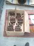
30 and more years of (perhaps too much) greasing and absence of maintenance (As it is impossible to access properly to all 6 brushes when the YG40 is not disassembled from the locomotive) have led to the situation that the brushes were not working properly anymore. Pressure exterted on the collector was not correct, leading either to a high wear of the carbon brushes (when these were blocked in their slide bar) and very dirty collector or to flashes when the pressure was not high enough.
The disassembling and reassembling of the brush holders was very "sporty" because of some mistakes in the construction of the assembly. But now the brush holders and the collector are bright and clean and everything is reassembled again. :-)"
|
